Interfacing Raspberry Pi and LPC1114FN28 via SPI
In one of my previous posts, i mentioned about building a toy car project using Raspberry Pi as the brain and the LPC1114FN28 for low level control. This post describes in detail of this hobby project.
Basically, in this project, the Raspberry Pi (running a minimal version of Debian, not Rasbian) acts as a master that :
- performs some high level calculation (software algorithm) base on the data it collects from the LPC chip (slave)
- Issues a control command to the slave chip (LPC) for low level control
- Reading image from Raspberry Camera for some vision stuffs
- Takes care of network communication for remote control
- Implements easily a lot of funny stuffs...
One question: why do not use the Pi to communicate directly with sensor or actuator ?. Although the Pi is a pretty performance system, it lacks some low level feature that we will need in this project, such as ADC for reading analog sensors, precise PWM hardware controller for motor control, etc. Therefore, i decided to used it along with the LPC chip that is more suitable for these low level stuffs.
Requirements
So what features do we need for such a project ?
First, let talk about the interface between the PI and the LPC1114FN28:
- The firmware on the LPC chip will be frequently changed during the development or update, we will need a mechanism to facilitate the deployment of firmware on the chip from the Pi. The approach i used is based on the approach presented in this post that uses the UART interface. Furthermore, the serial line could be used to log debug message from the LPC chip to the Raspberry Pi. This feature is useful in the firmware development process.
- The main communication between the Master and slave is via the SPI interface using a predefined protocol which will be detailed in latter section. The Raspberry Pi has two SPI ports, in this project we will use the SPI0 for the interface
Second, let take a closer look at the LPC1114FN28. Its main duty is to collect sensor data and control motors. Connecting to sensors are done by exposing all available GPIO and interface (e.g. I2C) as external connectors for future use in a specific application. To control motor, we need however a dedicated IC controller for this purpose. In this work we use the SN754410NE motor controller that allows to control up to 2 motors.
Last, since both devices can be powered using 3.3V supply (see this post to know how to do this on Raspberry Pi), we will need a voltage regulator to regulate input power from external battery to 3.3V supply. We will use the MCP1826S LDO voltage regulator for this purpose.
To sum up, this is the BOM (Bill of materials):
- Rapsberry Pi Zero
- LPC1114FN28
- SN754410NE motor controller
- MCP1826S LDO
- Some capacitors
Schematic & PCB
To design the schematic, it took me two days to learn to use KiCad, this is the schematic i finally came up with:
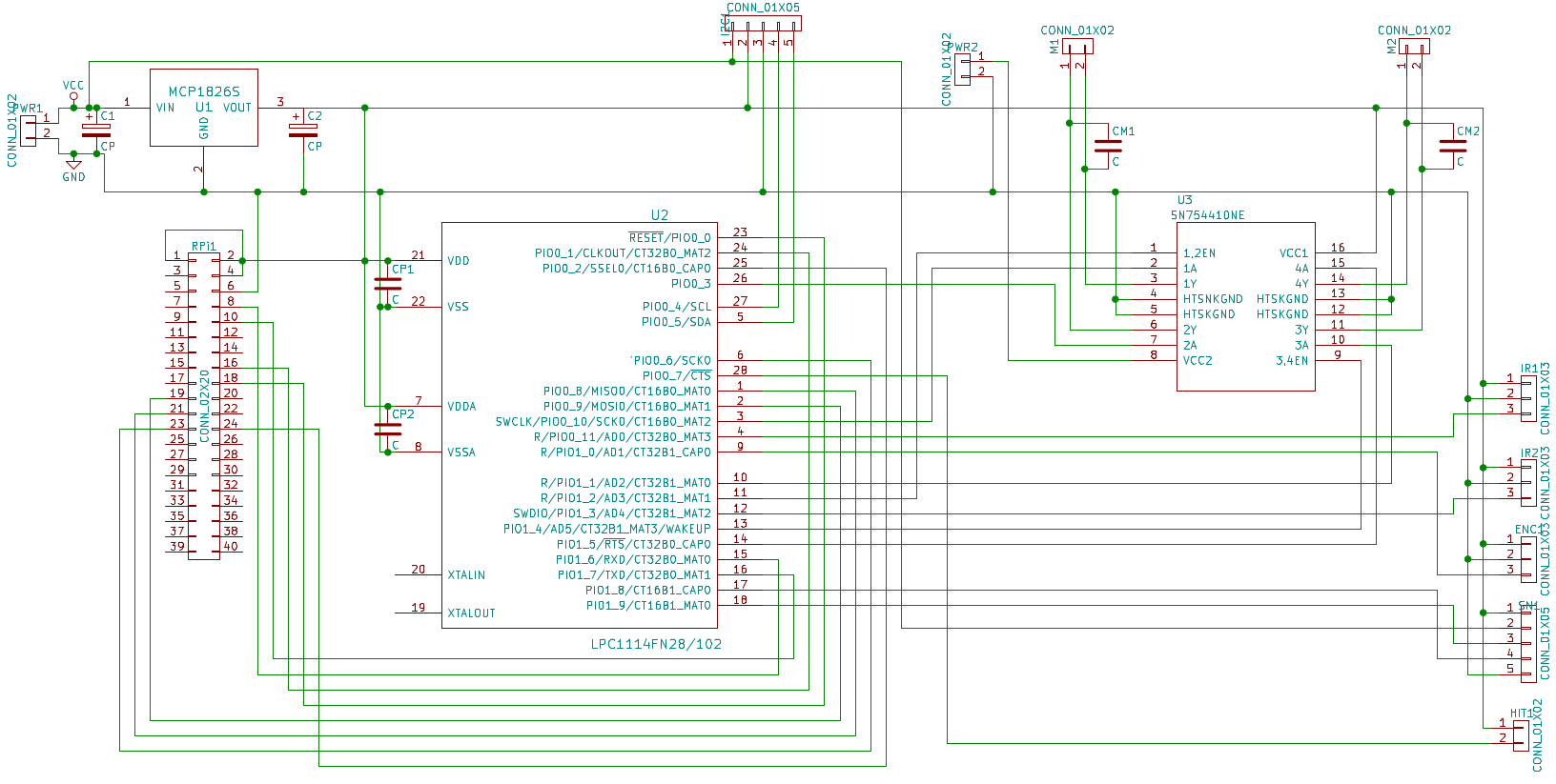
(Click the image for the full size schematic)
The 3.3V line output from the LDO is feed to both the Pi and the LPC chip, to power the SN754410NE motor controller, we use two power lines, one from the raw battery output to power the motors, and the other from the regulated 3.3V to power the IC.
The UART and SPI interface between the Pi and the LPC chipset are wired as follow:
| Raspberry Pi | LPC1114FN28 | Note |
|---|---|---|
| GPIO_15/UART0 RXD | PIO1_6/TXD | UART |
| GPIO_14/UART0 TXD | PIO1_7/RXD | UART |
| GPIO_24 | PIO0_0/RESET | Chip reset |
| GPIO_23 | PIO0_1 | ISP mode control |
| GPIO_9 | PIO0_8 | MISO0 |
| GPIO_10 | PIO0_9 | MOSI0 |
| GPIOP_11 | PIO0_10 | SCK0 |
| GPIO_8 | PIO0_2/SSEL0 | SPI selection |
The wiring between the SN754410NE and the LPC chip is as follow
| PLC1114FN28 | SN754410NE | Note |
|---|---|---|
| PIO1_2 | 1,2EN | PWM for motor 1 |
| PIO0_10 | 1A | Motor 1 direction |
| PIO0_3 | 2A | Motor 1 direction |
| PIO1_4 | 3,4EN | PWM for motor 2 |
| PIO1_1 | 3A | Motor 2 direction |
| PIO1_5 | 4A | Motor 2 direction |
All available GPIOs and interface (e.g. I2C) are exposed as external connectors. These connectors are reserved for future use such as connecting to sensor (ADC, sonar, I2C sensors etc.)
After playing around with the PCBNew tools available in Kicad, i ended up with a two layers PCB design ready for production:
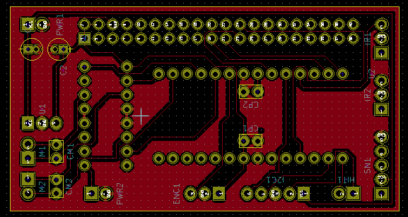
(First layer: The front of the PCB)
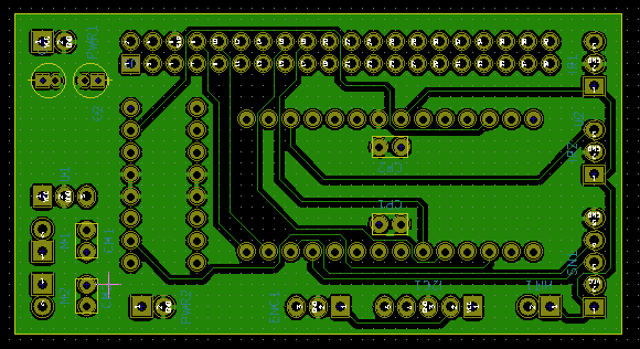
(Second layer: the back of the PCB)
Next step is to produce real PCB from the design, i've sent the design to a Chinese PCB Fab for production, the design is totally valid, no modification needed. The PCBs came two weeks later, here are two of them:
Assembly
Assembly all the parts to the PCB require some soldering. The PCB fits well on top of the Rasberry Pi, this is the final toy car hardware ready for programming:
In this first prototype, i connect only one sonar sensor to the LPC chip via an external connector, further sensors can be easily added via these connectors. Further more, all available raspberry GPIOs are also exposed for future upgrade if needed.
Software development
Software development on such system involves two main parts: (1) firmware for the LPC chip and (2) user application on Rapsberry Pi. These two part communicates with each other via a common communication protocol. This protocol needs to be as general as possible so that change on each part doesn't break it. Basically, when the Pi need to read sensors data or need to control actuators (motor), it issues a command to the slave chip (LPC one). This latter then returns the data of sensor or performs the action on the real actuators. So, there are two possible implementation choices for this communication:
- Whenever the master (Pi) requires data or action, the LPC chip performs a read on sensor devices or write on actuator devices to perform the command. This operation happens occasionally per master request
- The slave chip performs the sensors read or actuators write frequently and independently, latest sensor data/ actuator actions are stored in/fetched from an internal buffer. When the master issues a command, it actually reads or writes the data from/to this buffer. For example, a possible scenario: in each operation cycle (in the main loop) the slave chip independently reads data from a sonar sensor and stores this information at the index 0 of the internal buffer, then fetches the action for a motor at index 3 of the buffer to control the motor. When the Pi wants to know the sonar distance value, it issues a command that reads the data stored in the index 0 of the buffer (which contains the latest value of the sonar sensor). Similarly, when the Pi wants to control the motor, it writes a value to the index 3 of the buffer, which consequently changes the action that will lately be performed by the slave chip.
Although the first option seams simple to implement, it may lead to the timing problem when considering the interface we use. The SPI interface between the two devices are in full duplex mode, which means the transmission of data is in two directions simultaneously. That said, the Pi will immediately receives a returned byte when sending a byte to the slave. In the first option, a sensor read or actuator write operation is performed whenever there is a command from the master device, these operations introduce often a processing delay, which leads to the timing problem in SPI communication (e.g. the master receives junk data before the sensor data becomes available).
The second option avoids this problem by the use of a buffer, the master and slave communicate only via this buffer. When the master issues a command, it receives immediately the data stored in that buffer. This operation is often occasionally and can be implemented using hardware interrupt (SPI interrupt), while sensor reading and actuator control are performed frequently in the main loop of the slave.
In this case, the communication protocol is pretty simple: read from and write to the buffer. So we define a 3 bytes command (issued by the Pi) as follow
[CMD][INDEX1][VALUE/INDEX2]
CMD:
    0x0: read data from the position INDEX1 of the buffer
        Operation:
            1. The master sends 3 bytes command to inform the slave that
                it needs to read data at INDEX1, it then receives 3
                dummy bytes from the slave
            2. The master sends 3 dummy bytes to the slave and receives
                3 bytes in which the first byte contains the value requested
                follow by 2 dummy bytes

    0x1: write data VALUE to the INDEX1 of the buffer
        Operation:
            1. The master sends 3 bytes command to inform the slave that
                it needs to write to the buffer at INDEX1, the write is
                perfomed immediately by the slave and 3 dummy
                bytes are returned to the master

    0x2: read the buffer from the INDEX1 to the INDEX2
        Operation:
            1. The master sends 3 bytes command to inform the slave that
                it needs to read INDEX2 - INDEX1 bytes begining from INDEX1,
                it then receives 3 dummy bytes from the slave
            2. The master send INDEX2-INDEX1 dummy bytes to the slave and
                receives immediately  INDEX2-INDEX1 bytes from the buffer
                begining at INDEX1
Base on this description, the protocol can be implemented as follow:
LPC111x firmware
Firmware development on the LPC chip is previously described at this post, in this work, we will use the library available on my github repository
#include <stdio.h>
#include <stdlib.h>
#include <string.h>

#include <cpu.h>

#include "delay.h"

// We allocate the buffer of 64 bytes
#define BUF_SIZE 64
// The command size is 3 bytes
#define CMD_SIZE 3
uint8_t data_buffer[BUF_SIZE];
uint8_t cmd[CMD_SIZE];

/*
The command handler is perfomed via the SPI interrupt
When the iterrupt happens
*/
void SPI0_IRQHandler(void)
{
    uint8_t *p;
    int i;
    p = (uint8_t *) &cmd;
    //  first, read 3 bytes command
    for (i = 0; i < CMD_SIZE; i++)
    {
        while (!(LPC_SSP0->SR & 0x04));
        *p++ = LPC_SSP0->DR;
    }
    // Perform different action based on the cmd[0] value
    switch(cmd[0])
    {
        case 0:
            // read by index
            // return 3 bytes, first byte is the requested value
            while (!(LPC_SSP0->SR & 0x02));
            LPC_SSP0->DR = data_buffer[cmd[1]];
            break;

        case 1:
            // write by index
            // write data to specific index
            data_buffer[cmd[1]] = cmd[2];
            break;
        case 2:
            // read all data from INDEX1 to INDEX2
            for(i = cmd[1]; i < cmd[2];i++)
            {
                while (!(LPC_SSP0->SR & 0x02));
                LPC_SSP0->DR = data_buffer[i];
            }
            break;
        default:;
    }

    // Drain the receive SPI FIFO
    while (LPC_SSP0->SR & 0x04) (void) LPC_SSP0->DR;
}
Then in the main function:
int main(void)
{
    // init the chip at specific frequency
    cpu_init(DEFAULT_CPU_FREQ);
    //init spi
    if ((status = spi_slave_init(0, 8, 3, SPI_MSBFIRST)))
    {
        printf("ERROR: spi_master_init() failed at line %%d, %%s\n",
                    status, strerror(errno));
        exit(1);
    }
    // enable the interrupt on SPI0
    NVIC_EnableIRQ(SSP0_IRQn);
    // enable interrupt
    LPC_SSP0->IMSC |= (1<<1);

    // do other init stuff here

    // main loop
    for(;;)
    {
        /*
            perform the sensor read and actuator control here
        */
    }
Raspberry pi example
The following code shows an implementation of basic functions for the protocol on the Rapsberry Pi : spi_set, spi_get, spi_read_buff, spi_write_buff, spi_send_cmd
#include <stdint.h>
#include <unistd.h>
#include <stdio.h>
#include <stdlib.h>
#include <getopt.h>
#include <fcntl.h>
#include <sys/ioctl.h>
#include <linux/types.h>
#include <linux/spi/spidev.h>

#define ARRAY_SIZE(a) (sizeof(a) / sizeof((a)[0]))

static const char *device = "/dev/spidev0.0";
static uint8_t mode;
static uint8_t bits = 8;
static uint32_t speed = 500000;
static uint16_t delay = 110;

// init the spi
int spi_open()
{
    int ret;
    int fd = open(device, O_RDWR);
    if (fd < 0)
    {
        perror("can't open device \n");
        return -1;
    }
    /* spi mode*/
    ret = ioctl(fd, SPI_IOC_WR_MODE, &mode);
    if (ret == -1)
    {
        perror("can't set spi mode \n");
        return -1;
    }

    ret = ioctl(fd, SPI_IOC_RD_MODE, &mode);
    if (ret == -1)
    {
        perror("can't get spi mode \n");
        return -1;
    }
    /* bits per word*/
    ret = ioctl(fd, SPI_IOC_WR_BITS_PER_WORD, &bits);
    if (ret == -1)
    {
        perror("can't set bits per word \n");
        return -1;
    }
    ret = ioctl(fd, SPI_IOC_RD_BITS_PER_WORD, &bits);
    if (ret == -1)
    {
        perror("can't get bits per word");
        return -1;
    }
    /* max speed hz*/
    ret = ioctl(fd, SPI_IOC_WR_MAX_SPEED_HZ, &speed);
    if (ret == -1)
    {
        perror("can't set max speed hz");
        return -1;
    }
    ret = ioctl(fd, SPI_IOC_RD_MAX_SPEED_HZ, &speed);
    if (ret == -1)
    {
        perror("can't get max speed hz");
        return -1;
    }

    printf("spi mode: %%d\n", mode);
    printf("bits per word: %%d\n", bits);
    printf("max speed: %%d Hz (%%d KHz)\n", speed, speed/1000);

    return fd;
}
// issue a command to slave
int spi_send_cmd(int fd, uint8_t cmd, uint8_t idx, uint8_t value)
{
    int ret;
    uint8_t tx[3];
    uint8_t rx[3] = {0, };
    struct spi_ioc_transfer tr = {
        .tx_buf = (unsigned long)tx,
        .rx_buf = (unsigned long)rx,
        .len = 3,
        .delay_usecs = delay,
        .speed_hz = speed,
        .bits_per_word = bits
    };
    tx[0] = cmd;
    tx[1] = idx;
    tx[2] = value;
    ret = ioctl(fd, SPI_IOC_MESSAGE(1), &tr);
    if (ret < 1)
    {
        perror("can't send spi message");
        return -1;
    }
    //if(cmd == 255)
    // printf("RX %%d %%d %%d \n", rx[0], rx[1], rx[2]);
    return (int) rx[0];
}
// set a byte at specific index
int spi_set(int fd,uint8_t idx, uint8_t v)
{
    return spi_send_cmd(fd,1, idx, v);
}
// get a byte at specific index
int spi_get(int fd,uint8_t idx)
{
    // send command
    int ret;
    ret = spi_send_cmd(fd,0,idx,0);
    if(ret == -1) return -1;
    // read back
    return spi_send_cmd(fd,255,255,255);
}
// read buffer with a size
void spi_read_buff(int fd,uint8_t* buf, int size)
{
    int ret;
    uint8_t tx[size];
    struct spi_ioc_transfer tr = {
        .tx_buf = (unsigned long)tx,
        .rx_buf = (unsigned long)buf,
        .len = size,
        .delay_usecs = delay,
        .speed_hz = speed,
        .bits_per_word = bits
    };
    spi_send_cmd(fd,2,0,size);
    ret = ioctl(fd, SPI_IOC_MESSAGE(1), &tr);
    if (ret < 1)
    {
        perror("can't send spi message");
        return;
    }
}
// write buffer
void spi_write_buff(int fd, uint8_t* buf, int size)
{
    int i;
    for(i=0; i < size; i++)
        spi_set(fd,i,buf[i]);
}
...
This implementation is used as base protocol for my future application on the programmable toy car. The source code (schematic, PCB, firmware example) can be found on my github page
Related posts
- Programming the LPC1114FN28 using Raspberry Pi (Score: 0.21)
- Control GPIO using the new Linux user space GPIO API (Score: 0.20)
- Programming LPC1114FN28 with standard C using Newlib (Score: 0.18)
- Arm-cortex m0 programming with LPC1114FN28 , a guild to GPIOs (Score: 0.15)
- ARM-Cortex M0 programming with lpc1114FN28 - an overview (Score: 0.15)
- Monitoring and collecting syslog messages from Unix Domain Socket (Score: 0.13)
- Powering the Raspberry PI A+ with 4xAA batteries (Score: 0.13)
- sysmond: Simple service for (embedded) Linux system monitoring (Score: 0.12)
- Jarvis Arduino firmware (Score: 0.11)
- WVNC: web based protocol and API for accessing VNC server from browser via websocket (Score: 0.11)
- Meet Dolly the robot (Score: 0.08)